Jailbreaking the BLESense - pt.2 - sensors
Last updated: 2023-03-15
This is the second part of the post about jailbreaking the BLESense board.
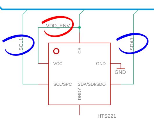
Here I will explain how to get the onboard sensors to work: how they are wired and how to use them. They require some pins to be switched on, for the I2C bus and the actual sensors to be active.
It has to be specified that this is about the original BLESense, not the new v2 (which has different sensors and possibly different PCB setup).
As explained in the previous post you can jailbreak the BLE Sense.
- use nRF52840 examples
- check the schematics
https://github.com/arduino/ArduinoCore-mbed/blob/master/variants/ARDUINO_NANO33BLE/pins_arduino.h
https://content.arduino.cc/assets/NANO33BLE_V2.0_sch.pdf
add simple BLUE LED blinking code that looks like in the GIF video
And now what?
- What to do next:
- memory.x and SoftDevice
https://learn.adafruit.com/introducing-the-adafruit-nrf52840-feather/hathach-memory-map
As you can see in the diagrams, the SoftDevice takes up space at the bottom of FLASH and RAM, so the values must be offset there.
MEMORY
{
  FLASH (rx): ORIGIN = 0x26000,    LENGTH = 0xED000 - 0x26000
  RAM (rwx):  ORIGIN = 0x20003400, LENGTH = 0x20010000 - 0x20003400
}
- embedded target definition
https://rust-embedded.github.io/blog/2018-08-2x-psa-cortex-m-breakage/ - need to read this and experiment
[build]
target = "thumbv7em-none-eabihf"
rustflags = ["-C", "link-arg=-Tlink.x"]
-
nRF-HAL
-
how to flash:
- build the code:
cargo build --release - convert to .hex file:
arm-none-eabi-objcopy -O ihex target/thumbv7em-none-eabihf/release/blinky blinky.hex - create a dfu package:
adafruit-nrfutil dfu genpkg --dev-type 0x0052 --application blinky.hex blinky.zip - put the board into bootloader mode (double click on reset button, will show up as NANO33BOOT or similar)
- flash the firmware:
adafruit-nrfutil dfu serial --package blinky.zip -p /dev/ttyACM0 -b 115200
- build the code:
-
simple blinkenlight
-
How to get the sensors to work?
Categories: rust embedded arduino tinyml